
![[IoT] Some demonstrations about controlling IoT devices](/content/images/2023/02/00-01.PNG)
1. Introduction
In this blog, we will demonstrate how to use some IoT devices such as Relay, LCD, and Servo Motor which combined with Raspberry Pi.
2. Demonstrations
2.1. Relay
2.1.1. Relay with LED
Work Principle
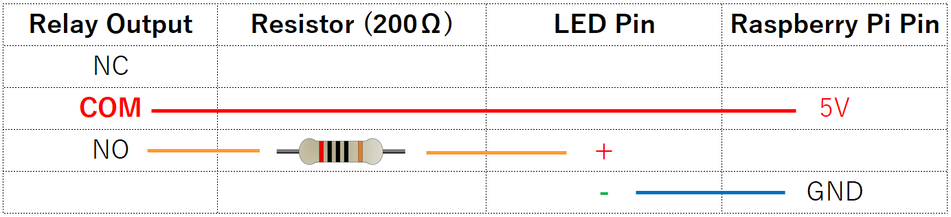
Relay is an electronic switch which allows low power digital signal to turn on/off a high power circuit. A relay has at least one pair of input pins and one pair output pins (output switch). When input gets digital signal 1 (high voltage), Relay will make output switch on. If Input pins get digit zero, it will make output switch off.
The construction and working of a relay can be understood from the below diagram.
Hardware Preparation
- Raspberry Pi x 01
- Breadboard x 01
- Relay x 01
- LED x 01
- Resistor (200Ω) x 01
- Several jumper wires
- T-Extension Board with 40-Pin Cable (Optional) x 01
Implementation
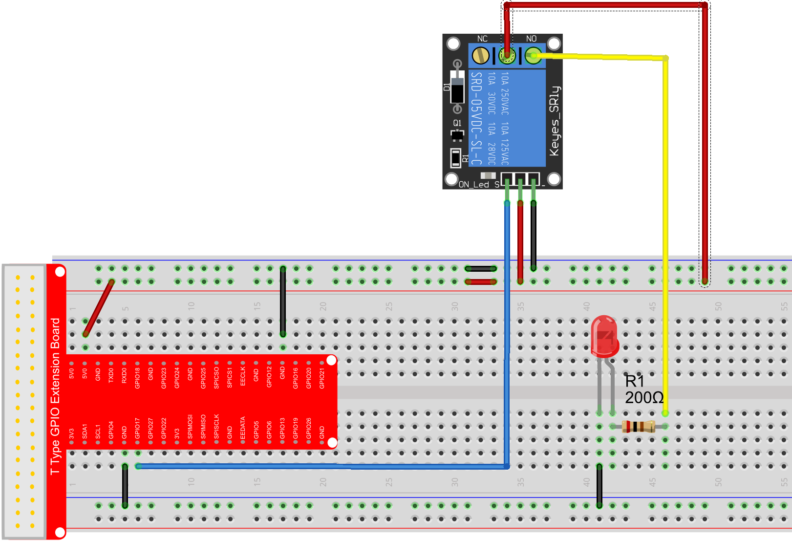
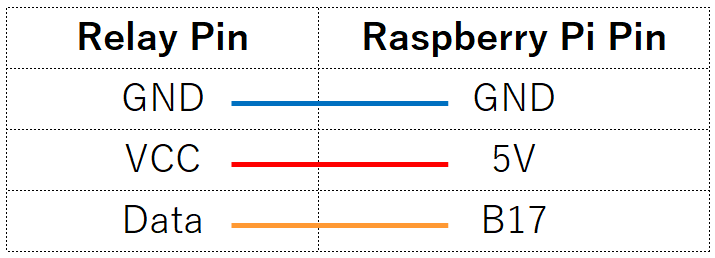
- Schematic diagram

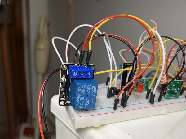
- In reality
- Coding
# relay_with_led.py
import RPi.GPIO as GPIO
import time

# set BCM_GPIO 17 as relay pin
RelayPin = 17

#print message at the begining ---custom function
def print_message():
    print ('|**********************************************|')
    print ('|                     Relay                    |')
    print ('|        -----------------------------------   |')
    print ('|        GPIO0 connect to relay control pin    |')
    print ('|        led connect to relay NormalOpen pin   |')
    print ('|        5V connect to relay COM pin           |')
    print ('|        Make relay to control a led           |')
    print ('|        -----------------------------------   |')
    print ('|                                              |')
    print ('|                                        OSOYOO|')
    print ('|**********************************************|\n')
    print ('Program is running...')
    print ('Please press Ctrl+C to end the program...')
    print ('\n')

#setup function for some setup---custom function
def setup():
    GPIO.setwarnings(False)
    #set the gpio modes to BCM numbering
    GPIO.setmode(GPIO.BCM)
    #set RelayPin's mode to output,and initial level to LOW(0V)
    GPIO.setup(RelayPin,GPIO.OUT,initial=GPIO.LOW)

#main function
def main():
    #print info
    print_message()
    while True:
        print ('|******************|')
        print ('|  ...Relay close  |')
        print ('|******************|\n')

        #disconnect
        GPIO.output(RelayPin,GPIO.LOW)
        time.sleep(1)

        print ('|*****************|')
        print ('|  Relay open...  |')
        print ('|*****************|\n')
        print ('')
        #connect
        GPIO.output(RelayPin,GPIO.HIGH)
        time.sleep(1)
        # GPIO.output(RelayPin,GPIO.LOW)
        # break # For testing...

#define a destroy function for clean up everything after the script finished
def destroy():
    #turn off relay
    GPIO.output(RelayPin,GPIO.LOW)
    #release resource
    GPIO.cleanup()
#
# if run this script directly ,do:
if __name__ == '__main__':
    setup()
    try:
            main()
    #when 'Ctrl+C' is pressed,child program destroy() will be executed.
    except KeyboardInterrupt:
        destroy()
Demo Video
![[IoT] Relay with LED (Raspi)](https://blog.shiftasia.com/content/images/2023/02/02-01-01-05.PNG)
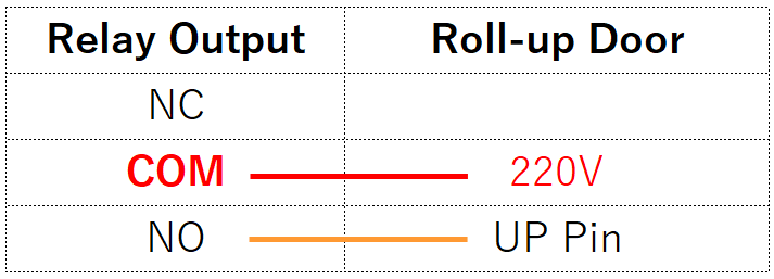
2.1.2. Relay with Roll-up door
I will use my Roll-up door instead of LED.
Hardware Preparation
- Raspberry Pi x 01
- Breadboard x 01
- Relay x 01
- Roll-up door x 01
- Several jumper wires
- T-Extension Board with 40-Pin Cable (Optional) x 01
Implementation
- Schematic diagram
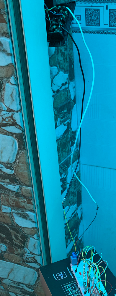
- In reality
- Coding
→ Same as 2.1.1. Relay with LED.
Demo Video
![[IoT] Relay with roll up door (Raspi)](https://blog.shiftasia.com/content/images/2023/02/02-01-02-03.PNG)
2.2. LCD
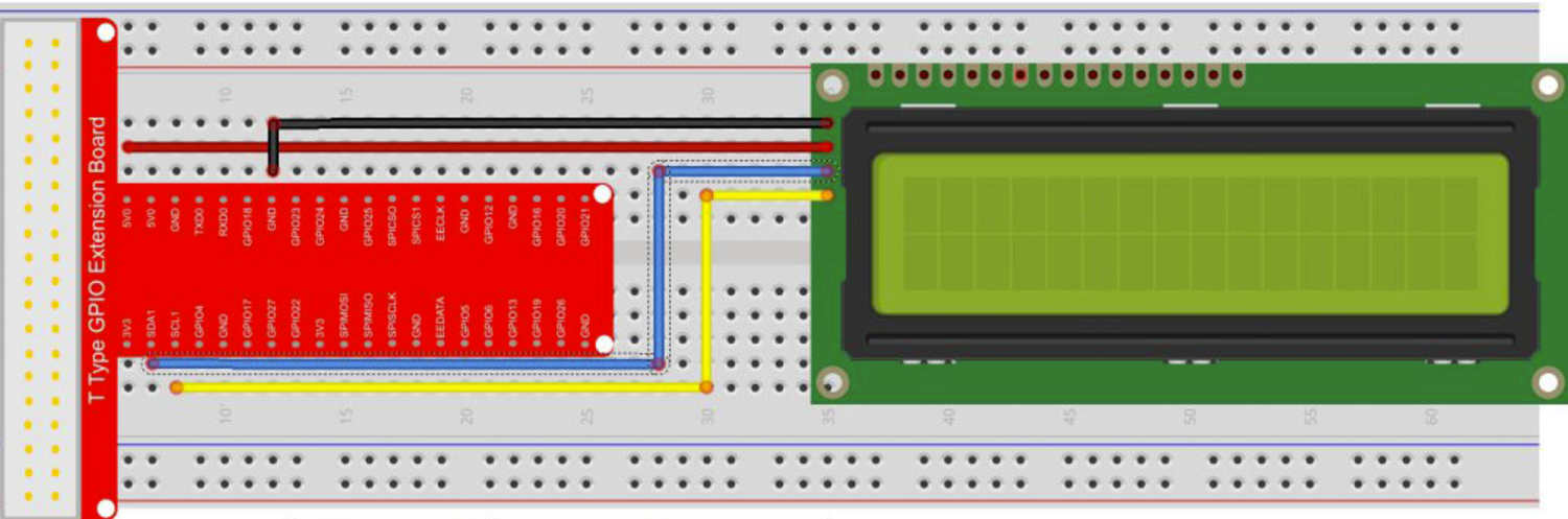
In this demo, we'll introduce how to drive IIC (sometimes call I2C) 1602 LCD using Raspberry Pi.
Work Principle
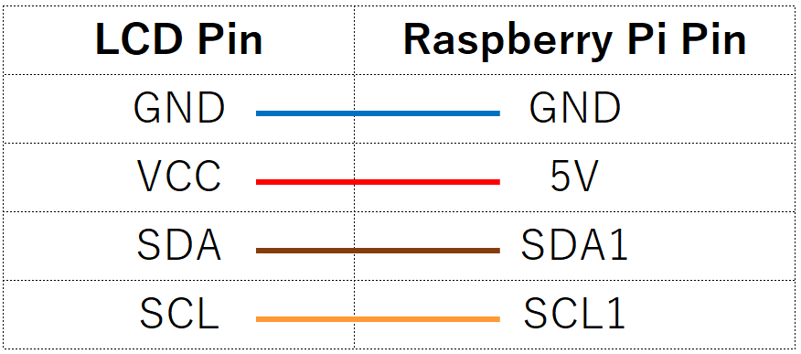
The 1602 LCD display screen can display 16 (each row) x 2 (rows) characters. Generally, LCD 1602 has parallel port, it occupy many GPIO pins. This 1602 LCD comes with a I2C communicate interface using a PCF8574 IC Chip. It means you can realize data display via only 2 wires.
Hardware Preparation
- Raspberry Pi x 01
- Breadboard x 01
- IIC 1602 LCD (16 x 2 characters) x 01
- Several jumper wires
- T-Extension Board with 40-Pin Cable (Optional) x 01
Implementation
- Schematic diagram
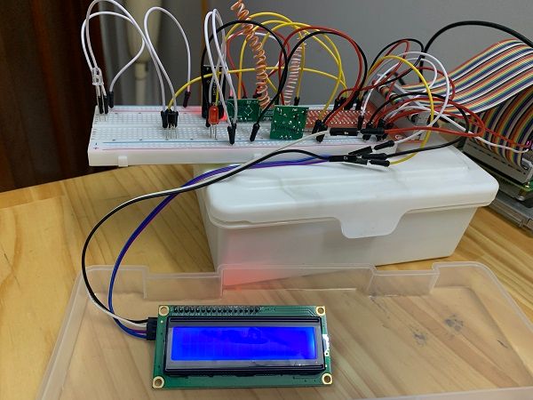
- In reality
- Coding
To use the I2C 1602 LCD, we should enable the I2C port firstly, please follow the steps as followed:
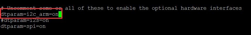
(1) Open I2C
sudo vim /boot/config.txt
Open the file /boot/config.txt, find the code line "dtparam=i2c_arm",checking if there is # sign in front of the line, uncomment it (remove the # in front of this line), and make sure the end of the line is "on", finally the code should look like this:
(2) Load Modules
sudo vim /etc/modules
Open /etc/modules file,add these two lines as below:
i2c-bcm2708
i2c-dev
(3) Install i2c python library and smbus
sudo apt-get install -y python-smbus i2c-tools
Now reboot Raspberry Pi by command sudo reboot
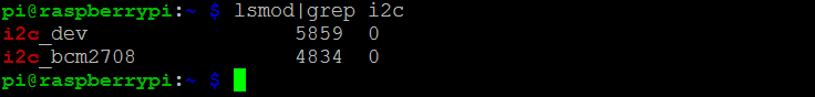
(4) Checking the if library is installed successfully by typing following command:
lsmod | grep i2c
(5) Checking for any components connected to the i2c bus by using i2c detect
sudo i2cdetect -y 1
     0  1  2  3  4  5  6  7  8  9  a  b  c  d  e  f
00:          -- -- -- -- -- -- -- -- -- -- -- -- --
10: -- -- -- -- -- -- -- -- -- -- -- -- -- -- -- --
20: -- -- -- -- -- -- -- 27 -- -- -- -- -- -- -- --
30: -- -- -- -- -- -- -- -- -- -- -- -- -- -- -- --
40: -- -- -- -- -- -- -- -- -- -- -- -- -- -- -- --
50: -- -- -- -- -- -- -- -- -- -- -- -- -- -- -- --
60: -- -- -- -- -- -- -- -- -- -- -- -- -- -- -- --
70: -- -- -- -- -- -- -- --
Source code
# i2c1602_lcd.py
import smbus
import time

# Define some device parameters
# I2C_ADDR  = 0x3F # I2C device address, if any error, change this address to 0x27
I2C_ADDR  = 0x27 # I2C device address, if any error, change this address to 0x27
LCD_WIDTH = 16   # Maximum characters per line

# Define some device constants
LCD_CHR = 1 # Mode - Sending data
LCD_CMD = 0 # Mode - Sending command

LCD_LINE_1 = 0x80 # LCD RAM address for the 1st line
LCD_LINE_2 = 0xC0 # LCD RAM address for the 2nd line
LCD_LINE_3 = 0x94 # LCD RAM address for the 3rd line
LCD_LINE_4 = 0xD4 # LCD RAM address for the 4th line

LCD_BACKLIGHT  = 0x08  # On
# LCD_BACKLIGHT = 0x00  # Off

ENABLE = 0b00000100 # Enable bit

# Timing constants
E_PULSE = 0.0005
E_DELAY = 0.0005

#Open I2C interface
#bus = smbus.SMBus(0)  # Rev 1 Pi uses 0
bus = smbus.SMBus(1) # Rev 2 Pi uses 1

def lcd_init():
  # Initialise display
  lcd_byte(0x33,LCD_CMD) # 110011 Initialise
  lcd_byte(0x32,LCD_CMD) # 110010 Initialise
  lcd_byte(0x06,LCD_CMD) # 000110 Cursor move direction
  lcd_byte(0x0C,LCD_CMD) # 001100 Display On,Cursor Off, Blink Off
  lcd_byte(0x28,LCD_CMD) # 101000 Data length, number of lines, font size
  lcd_byte(0x01,LCD_CMD) # 000001 Clear display
  time.sleep(E_DELAY)

def lcd_byte(bits, mode):
  # Send byte to data pins
  # bits = the data
  # mode = 1 for data
  #        0 for command

  bits_high = mode | (bits & 0xF0) | LCD_BACKLIGHT
  bits_low = mode | ((bits<<4) & 0xF0) | LCD_BACKLIGHT

  # High bits
  bus.write_byte(I2C_ADDR, bits_high)
  lcd_toggle_enable(bits_high)

  # Low bits
  bus.write_byte(I2C_ADDR, bits_low)
  lcd_toggle_enable(bits_low)

def lcd_toggle_enable(bits):
  # Toggle enable
  time.sleep(E_DELAY)
  bus.write_byte(I2C_ADDR, (bits | ENABLE))
  time.sleep(E_PULSE)
  bus.write_byte(I2C_ADDR,(bits & ~ENABLE))
  time.sleep(E_DELAY)

def lcd_string(message,line):
  # Send string to display

  message = message.ljust(LCD_WIDTH," ")

  lcd_byte(line, LCD_CMD)

  for i in range(LCD_WIDTH):
    lcd_byte(ord(message[i]),LCD_CHR)

def main():
  # Main program block

  # Initialise display
  lcd_init()

  while True:

    # Send some test
    lcd_string("Created by         <",LCD_LINE_1)
    lcd_string("Osoyoo.com        <",LCD_LINE_2)
    time.sleep(3)

    # Send some more text
    lcd_string("> Tutorial Url:",LCD_LINE_1)
    lcd_string("> http://osoyoo.com",LCD_LINE_2)
    time.sleep(3)

if __name__ == '__main__':

  try:
    main()
  except KeyboardInterrupt:
    pass
  finally:
    lcd_byte(0x01, LCD_CMD)
Demo Video
![[IoT] LCD with Raspi](https://blog.shiftasia.com/content/images/2023/02/02-02-06.PNG)
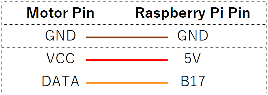
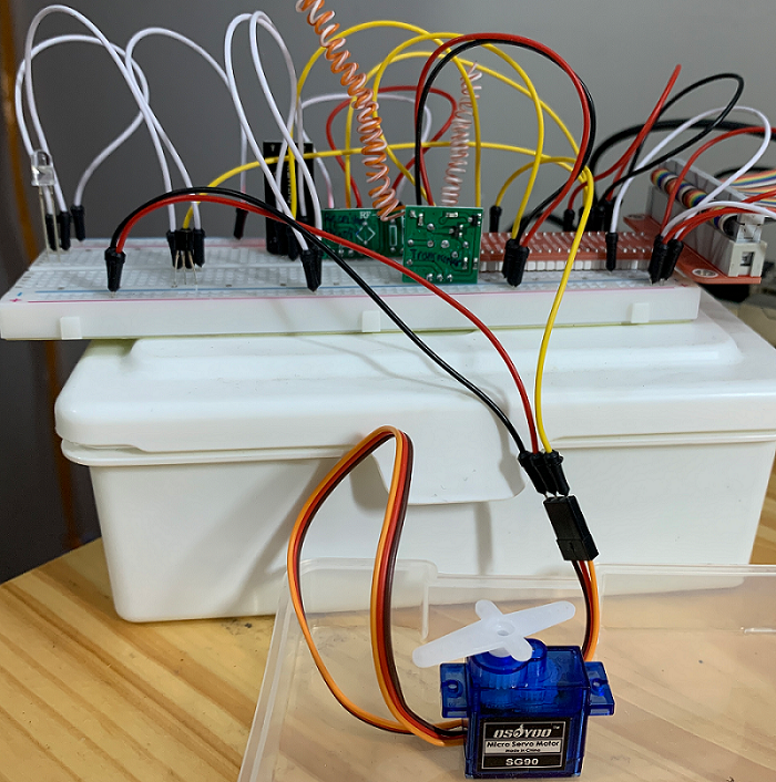
2.3. Servo Motor
In this demo, we will use Raspberry Pi to send command through GPIO to Servo Motor and control its rotation action.
Hardware Preparation
- Raspberry Pi x 01
- Breadboard x 01
- Servo Motor x 01
- Several jumper wires
- T-Extension Board with 40-Pin Cable (Optional) x 01
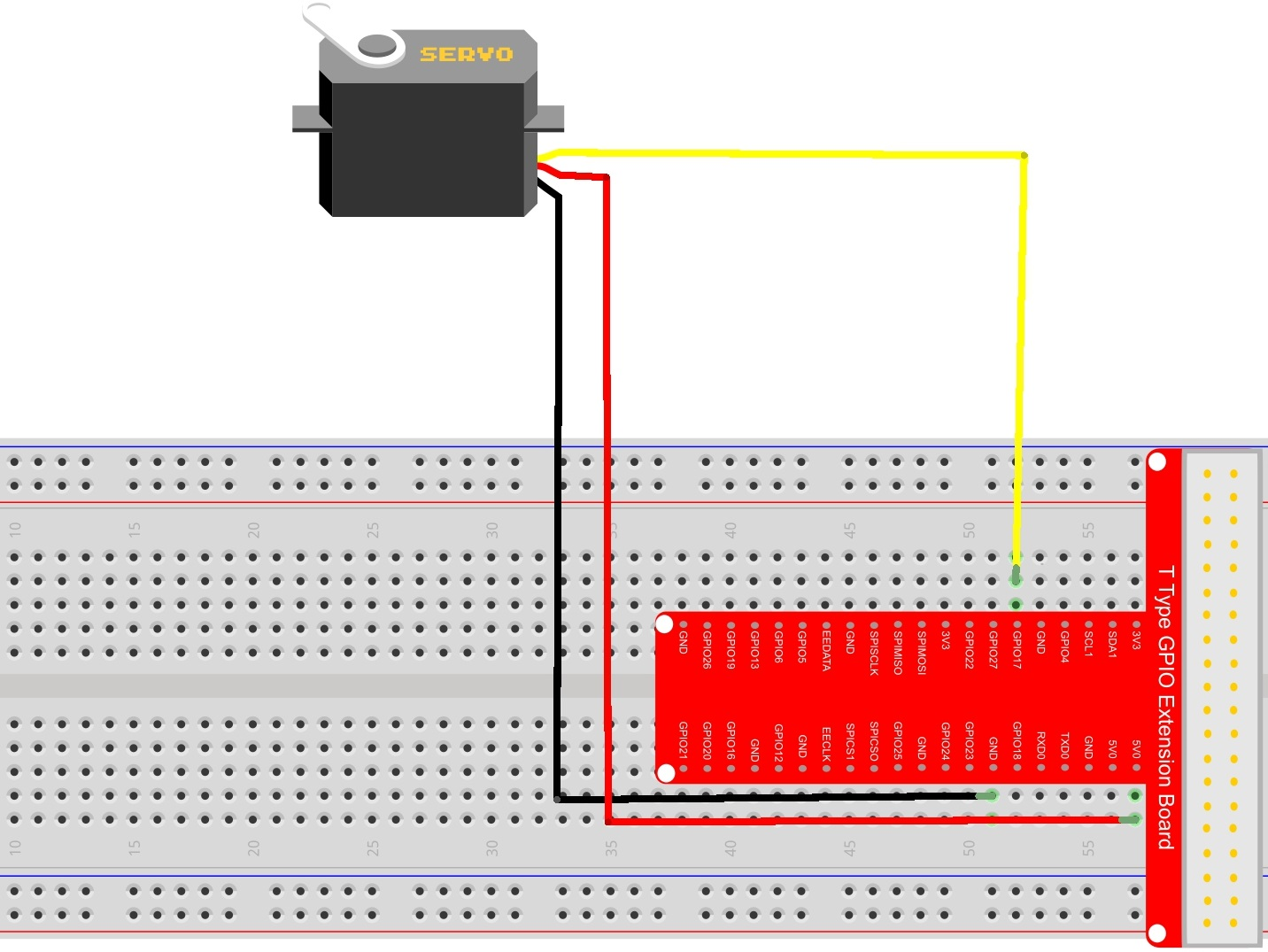
Implementation
- Schematic diagram
- In reality
- Coding
# pi-servo.py
import RPi.GPIO as GPIO
import time
import os

GPIO.setwarnings(False)
# Set the layout for the pin declaration
# GPIO.setmode(GPIO.BOARD)
GPIO.setmode(GPIO.BCM)
# The Raspberry Pi pin 11(GPIO 18) connect to servo signal line(yellow wire)
# Pin 11 send PWM signal to control servo motion
# GPIO.setup(11, GPIO.OUT)
PIN_NUM = 13
GPIO.setup(PIN_NUM, GPIO.OUT)

# menu info
print("l = move to the left")
print("r = move to the right")
print("m = move to the middle")
print("t = test sequence")
print("q = stop and exit")

# Now we will start with a PWM signal at 50Hz at pin 18.
# 50Hz should work for many servos very will. If not you can play with the frequency if you like.
Servo = None

def main():
    input_str = ""
    while True:
        Servo = GPIO.PWM(PIN_NUM, 50)
        # This command sets the left position of the servo
        Servo.start(2.5)

        # Now the program asks for the direction the servo should turn.
        input_str = input("Selection: ")
        print(f"========> {input_str}")

        # You can play with the values.
        # 7.5 is in most cases the middle position
        # 12.5 is the value for a 180 degree move to the right
        # 2.5 is the value for a -90 degree move to the left
        if(input_str == "t"):
            print("move to the center position:")
            Servo.ChangeDutyCycle(7.5)
            time.sleep(1)
            print("move to the right position:")
            Servo.ChangeDutyCycle(12.5)
            time.sleep(1)
            print("move to the left position:")
            Servo.ChangeDutyCycle(2.5)
            time.sleep(1)
            # this stops the PWM signal
            print("Move back to start position.")
            Servo.stop()
            Servo = None
            continue

        # direction right
        if(input_str == "r"):

            # how many steps should the move take.
            steps = str(input("steps (1 - 10): "))
            print(steps, "steps to the right")
            stepslength = 12.5 / int(steps)
            for Counter in range(int(steps)):
                Servo.ChangeDutyCycle(stepslength * (Counter + 1))
                print(stepslength * (Counter + 1))
                time.sleep(0.5)

            time.sleep(1)
            # PWM stop
            print("Move back to start position.")
            Servo.stop()
            Servo = None
            continue

        # move to the center position
        elif(input_str == "m"):
            print("Move back to the center position.")
            Servo.start(7.5)
            time.sleep(1)
            # PWM stop
            print("Move back to start position.")
            Servo.stop()
            Servo = None
            continue

        # move to the left
        elif(input_str == "l"):
            print("Move  to the max right position and then to the left position.")
            Servo.start(12.5)
            # how many steps...
            steps = str(input("steps (1 - 10): "))
            print(steps, "steps to the right")
            stepslength = 12.5 / int(steps)
            for Counter in range(int(steps)):
                Servo.ChangeDutyCycle(12.5 - (stepslength * (Counter + 1)))
                print (12.5 - (stepslength * (Counter + 1)))
                time.sleep(0.5)

            time.sleep(1)
            # PWM stop
            print("Move back to start position.")
            Servo.stop()
            Servo = None
            continue

        # close program
        elif(input_str == "q"):
            print("stop the program and exit......")
            destroy()

        # input not valid
        else:
            print("input not valid!")
            Servo.stop()
            Servo = None

#define a destroy function for clean up everything after the script finished
def destroy():
    if Servo:
        Servo.stop()
    #release resource
    GPIO.cleanup()
    os._exit(1)

# if run this script directly ,do:
if __name__ == '__main__':
    try:
        main()
    # when 'Ctrl+C' is pressed,child program destroy() will be executed.
    except KeyboardInterrupt:
        destroy()
Demo Video
![[IoT] [IoT] Motor with Raspi](https://blog.shiftasia.com/content/images/2023/02/02-03-05.PNG)
5. Summary
With demos above, you may find that connecting and controlling IoT devices is also quite simple, which will be able to help you deploy your own IoT projects easily.